
Diagnose the Pilot Problem Before You Change the Flame Sensor
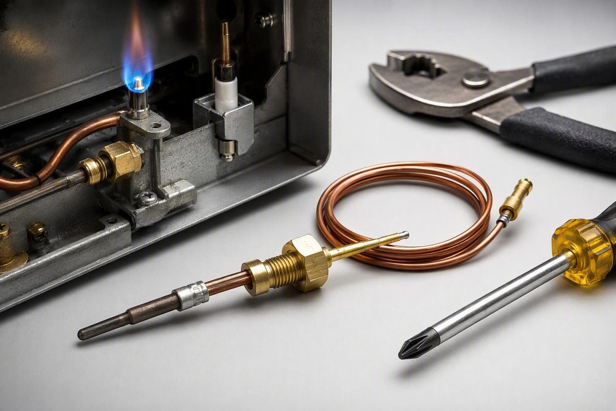
A pilot that lights but goes out when you release the control is often blamed on the thermocouple. That is a reasonable possibility, not a complete diagnosis. A weak or obstructed pilot flame, soot, poor sensor alignment, a loose connection, drafts, air in the gas line, a clogged pilot component, or a defective gas control valve can produce a similar symptom.
The safe approach to how to replace a thermocouple is to diagnose the pilot problem first, identify the appliance and sensor from the model documentation, obtain the exact compatible component, and let the appliance instructions control every model-specific step.
This guide is limited to standing-pilot gas appliances with a conventional, separately replaceable thermocouple—principally conventional gas tank water heaters and some gas fireplaces or stoves. It does not provide a detailed procedure for furnaces, boilers, ovens, electronic-ignition systems, or sealed-combustion appliances.
At a high level, replacement involves shutting down the appliance, accessing the pilot assembly, removing the old sensor, mounting and routing the replacement, testing every gas connection disturbed during access, and relighting the appliance according to its label. If you cannot positively identify the sensor, shutoff, connections, or correct procedure, stop and arrange qualified service.
First, Confirm This Is the Right Repair for Your Appliance
A conventional thermocouple is a flame-safety sensor positioned at a standing pilot. When heated, it produces a small electrical signal that permits gas-valve operation. If the pilot goes out and the sensor cools, the safety system is intended to stop gas flow. The thermocouple is therefore part of the appliance’s gas-safety circuit, not simply a temperature probe. AAA Home Services explains this operating principle in its water-heater thermocouple overview.
Use this guide only when all of the following are true:
- The appliance burns gas and has a standing pilot.
- The model documentation identifies the component as a conventional thermocouple.
- The thermocouple is a separately replaceable part.
- The appliance instructions permit access to it.
- You can identify the manual gas shutoff and all connections that the procedure requires you to disturb.
- You have the exact compatible replacement.
- You can perform the required post-repair leak checks.
Do not identify the sensor from appearance alone. Confirm the system through the appliance rating plate, owner’s manual, parts diagram, service literature, or manufacturer before disconnecting anything.
Record the following information:
- Manufacturer
- Complete model number
- Serial number, if needed to distinguish revisions
- Gas type
- Ignition or pilot-system description
- Original thermocouple part number, if present
- Warnings or service restrictions shown on the appliance
The appliance label and manufacturer instructions control part selection, access, flame position, tightening requirements, permitted leak-detection products, and relighting. A generic photograph or procedure cannot resolve model-specific differences.
The type of appliance also affects the scope:
Conventional gas tank water heater: Some models require removal of a burner assembly. That may involve disconnecting the thermocouple, pilot tube, burner line, or other specified connections before the assembly can be withdrawn. Other models use different access and retention arrangements. Water-heater thermocouples also vary in size and configuration, so the replacement must be matched to the exact model. Appliance Parts Pros illustrates these model-dependent differences in its water-heater procedure.
Gas fireplace or freestanding gas stove: Access, panel removal, pilot mounting, and valve location vary. Follow the model documentation rather than assuming that a water-heater procedure applies.
Furnace, boiler, oven, electronic-ignition appliance, or sealed-combustion unit: These are outside the detailed procedure here. Their controls, access requirements, and combustion enclosures may require a different method or qualified service.
Before beginning, answer three questions:
- What component does the parts diagram identify?
- What exact replacement is approved for the model?
- What model-specific procedure governs access and reassembly?
If any answer is uncertain, do not experiment. Obtain the correct documentation, contact the manufacturer, or call a qualified gas technician.
Diagnose the Pilot-Light Symptom Before Buying a Part
A failed thermocouple can cause a recognizable symptom, but that symptom has several possible causes.
If the pilot lights while you hold the control in the prescribed position but goes out after you release it, the flame-safety circuit is not being maintained. The thermocouple may be dirty, misaligned, loose, physically damaged, or electrically weak. The pilot flame may also be too weak or poorly directed to heat the sensor adequately. The symptom makes the thermocouple worth inspecting; it does not prove that the part has failed.
If the pilot does not ignite at all, investigate the pilot and gas supply before buying a thermocouple. Possible causes include:
- No gas reaching the appliance
- Incorrect control position
- Air in a recently interrupted gas line
- A blocked pilot tube or orifice
- Debris in the pilot assembly
- An ignition problem
- A gas-control fault
A cold thermocouple cannot maintain the safety valve, but it ordinarily does not create the pilot flame. That distinction helps prevent replacement of a sensor when the underlying problem is pilot-gas delivery or ignition.
Use this diagnostic sequence:
- Follow the lighting sequence printed on the appliance or stated in its manual.
- Observe whether the pilot ignites.
- If it ignites, confirm that it remains steady while the control is held.
- Compare the flame and sensor position with the model documentation.
- Release the control only after the appliance’s specified hold period.
- If the pilot goes out, inspect the thermocouple, its connection, its alignment, and the pilot flame before concluding that the part has failed.
A functioning pilot should be stable enough to heat the sensor in the position specified by the manufacturer. Look for soot, debris, corrosion, an obstructed flame, or a displaced sensor mount. Do not impose a universal flame color, flame-contact distance, or sensor depth; pilot designs differ.
Possible causes of pilot dropout include:
- Soot or carbon on the sensor
- Debris obstructing the pilot flame
- Incorrect thermocouple alignment
- A loose thermocouple connection
- A bent, crushed, or kinked thermocouple lead
- Drafts affecting the pilot
- Air in the gas line
- A clogged pilot tube or orifice
- A defective gas control valve
Cleaning may prevent unnecessary replacement. After shutting down the appliance, closing its gas supply, disconnecting applicable power, and allowing the assembly to cool, gently remove loose soot from the thermocouple if the manual permits access. Do not aggressively sand, gouge, reshape, or damage the sensor’s coating. The Home Depot’s general procedure recommends gentle soot or carbon removal and treats pilot dropout as a possible rather than conclusive thermocouple symptom.
It also cannot correct a pilot flame that fails to heat a properly positioned sensor.
A millivolt test is optional and should be used only when the appliance or gas-control manufacturer provides:
- The required meter setting
- The correct test points
- The prescribed heating method
- Whether testing is open-circuit or connected
- The acceptable range for that appliance and test condition
Third-party sources publish conflicting thermocouple thresholds. A fireplace or stove test described by one retailer, for example, cannot be converted into a universal pass/fail standard for water heaters or other gas controls. Mountain View Hearth Products’ procedure demonstrates how a millivolt figure depends on the test method being used.
Never wedge a control in position, bypass the gas valve, jumper a safety circuit, or otherwise defeat flame protection during diagnosis. If the manufacturer does not provide a supported test method, have the appliance tested professionally.
Shut the Appliance Down and Know the Stop-Work Rules
Do not open an appliance while it is operating, hot, or capable of starting automatically.
Unless the appliance instructions impose additional requirements:
- Turn the appliance off.
- Set the appliance gas control to OFF.
- Close the manual gas shutoff serving the appliance.
- Disconnect electrical power where applicable.
- Ensure that a thermostat, remote, timer, or other automatic control cannot start the appliance.
- Allow the burner, pilot assembly, and surrounding components to cool.
- Wait at least five minutes before beginning work, or follow the appliance’s longer stated waiting period.
General thermocouple guidance calls for shutting off gas and applicable electrical power, setting the control to OFF, allowing the appliance to cool, and waiting at least five minutes before work. The Home Depot also warns against relighting when gas is smelled or hissing is heard.
Gas-emergency rule: If you smell gas or hear hissing, do not light anything, operate electrical switches, create a spark, or continue the repair. Leave the affected area and contact the gas utility or emergency services from outside. Do not remain inside to locate the leak or collect tools. Appliance Parts Pros gives the same evacuation and outside-contact direction for suspected gas leaks in its safety guidance.
Repeated unsuccessful ignition attempts can release additional gas. After a failed attempt, return the control to the position stated on the appliance label and observe the full required waiting period before trying again.
Before removing a panel, make sure the manual shutoff you closed actually serves the appliance. The appliance control knob is not necessarily a substitute for the required manual supply shutoff.
Stop before disassembly if:
- You cannot identify or operate the correct shutoff.
- You cannot prevent automatic appliance operation.
- The valve, fitting, or tubing is corroded or visibly damaged.
- A connector is rounded, cross-threaded, or deformed.
- The burner compartment is sealed or inaccessible.
- The connections do not match the parts diagram.
- The appliance instructions require qualified service.
- Access would require forcing, cutting, drilling, or modifying a gas component.
- You do not have the specified method or product for leak testing.
The appliance manual and applicable local requirements take priority over this general overview. When the documentation limits service to qualified personnel, follow that direction.
Gather the Tools and Match the Replacement Exactly
Gather the required equipment before opening the appliance. A basic checklist includes:
- The exact model-compatible replacement thermocouple
- Correctly sized wrenches
- The screwdriver, nut driver, or other hand tools specified for the access panels and sensor mount
- A flashlight
- Manufacturer-approved leak-detection solution
- A clean, soft material for permitted soot removal
- Labels or removable tape for identifying connections
- A phone or camera for documenting the original arrangement
- The appliance manual and replacement-part instructions
A multimeter is optional. Include it only if the manufacturer provides the test procedure and acceptable range.
Match the replacement through the appliance model number, parts list, and original component. Check:
- Lead length
- Valve-side connector or thread
- Pilot-side bracket or clip
- Mounting arrangement
- Any required sleeves, adapters, retainers, or special fittings
- Manufacturer part number and approved substitutions
Thermocouples are not universally interchangeable. Similar-looking parts can differ in length, threads, fittings, or mounting. Precision Heating & Cooling specifically advises matching the original length, threads, and special fittings rather than selecting a replacement by appearance alone. Its water-heater guidance also notes that burner removal and line disconnection vary by model.
Before removal, photograph the pilot assembly, thermocouple position, lead route, valve connection, clips, and any connections the manual requires you to disturb. Label similar connections if necessary. Do this only under normal, gas-free working conditions; documentation must never delay evacuation when a leak is suspected.
If the approved replacement is longer than the original, follow its instructions for routing the excess. A gentle curve may be permitted, but sharp bends and kinks should be avoided. Never stretch a short lead to make it reach.
Do not:
- Force a connector into a valve
- Alter threads
- Modify the pilot bracket
- Splice the thermocouple lead
- Substitute a thermopile or electronic flame sensor
- Assume a package marked “universal” fits the appliance
- Use an adapter not approved for the model
If compatibility cannot be confirmed from the appliance documentation, manufacturer, or an authorized parts source, postpone the repair.
Remove the Old Thermocouple Without Damaging the Pilot Assembly
Begin only after the control is OFF, the manual gas supply is closed, applicable electrical power is disconnected, the waiting period has passed, and the appliance is cool.
Remove only the access covers identified in the appliance instructions. Keep the fasteners organized so each panel can be restored correctly.
Before loosening anything, trace the thermocouple from end to end:
- The sensor end is mounted at the pilot assembly.
- The lead runs back toward the gas control.
- The connector end terminates at the port identified in the appliance diagram.
Confirm the route against the parts diagram and your photographs. Do not disconnect a pilot tube, burner line, igniter wire, or another component on the assumption that it is the thermocouple.
A general removal sequence is:
- Photograph and label the original arrangement.
- Note the thermocouple’s mounting position and lead route.
- Identify every connection the model-specific procedure requires you to disturb.
- Loosen the thermocouple connector with the correctly sized tool.
- Release the pilot-side clip, screw, or bracket as designed.
- Remove the lead without yanking, twisting, or prying against the pilot assembly.
- Compare the removed component with the replacement.
If a connector does not move with controlled tool pressure, stop rather than rounding the fitting or damaging nearby components. At the pilot end, locate the actual retaining device and release it according to the appliance instructions.
Some conventional tank water heaters require removal of the complete burner assembly. On an applicable model, the instructions may require disconnection of the thermocouple, pilot tube, burner line, or other specified connections before the assembly is withdrawn. This is not a universal procedure for every water heater, fireplace, or stove.
Inspect the removed part and nearby components for:
- Damaged or cross-threaded connectors
- Cracked, bent, or flattened tubing
- Corrosion
- Soot accumulation
- Heat damage
- Missing retainers
- A distorted sensor mount
- Evidence that a fitting was previously forced or overtightened
Stop and obtain qualified service if a valve, gas tube, fitting, or connector appears damaged. Do not reinstall a compromised gas component simply because it was already in service.
Make a written list of every gas connection opened or loosened. Although the thermocouple connection itself carries its electrical signal to the control, pilot and burner lines disturbed during access carry gas. Every disturbed gas connection must be tested after reassembly.
Install and Route the New Thermocouple
Compare the old and new components side by side. Confirm that the mounting end, valve connector, lead length, threads, and required fittings match the appliance documentation.
Place the new sensor in the same model-approved bracket or mounting arrangement as the original. Secure it using the specified clip, screw, retainer, or fitting.
Route the lead along the original path, avoiding:
- Sharp edges
- Moving controls or linkages
- Burner ports
- Hot areas not used by the original route
- Locations where an access panel could pinch the lead
Use smooth curves. Do not twist the sensor body or sharply bend, crush, or kink the lead.
Position the sensor tip exactly as the appliance manufacturer specifies. There is no universal flame-contact distance or mounting depth for every appliance. Do not move the sensor into an undocumented position to compensate for a weak pilot flame; diagnose the pilot problem instead.
For a threaded connection:
- Align the connector squarely with the correct port.
- Start it by hand.
- Confirm that it turns smoothly without tilting or binding.
- Stop if the threads feel rough or resist engagement.
- Tighten it according to the appliance or replacement-part instructions.
- Do not overtighten.
Hand-starting helps avoid cross-threading, but it does not replace the final tightening required by the manufacturer.
If burner-assembly removal was required, return the assembly to its original position and reconnect only the lines identified in the model instructions. Place each connection in its original port; do not identify connections by approximate size alone.
Restore the specified brackets, retainers, access doors, wiring connections, and panels in the sequence required by the manual. Leave open only the access specifically needed for the prescribed leak and operating checks.
Leak-Test, Relight, and Verify the Repair
Reassembly is not complete until every disturbed gas connection has been inspected and tested. Do not test only the connection nearest the thermocouple. Include every pilot tube, burner line, manifold connection, or other gas joint opened or loosened during access.
Use the leak-detection product approved by the appliance manufacturer for the appliance and fitting materials. Do not assume that a household mixture is acceptable for every model.
With the controls in the position specified for testing:
- Confirm that all required connections have been restored.
- Restore the gas supply only as directed.
- Apply the approved leak-detection solution to every disturbed gas connection.
- Observe each connection carefully.
- Treat growing bubbles as evidence of a leak.
- Shut off the gas immediately if a leak appears.
- Correct the connection only if the required remedy is clear, permitted, and within your competence.
- Retest the connection before attempting ignition.
Growing bubbles indicate a leak that must be corrected before the appliance is lit. A persistent leak, damaged fitting, uncertain connection, or unsuccessful correction requires professional service. Precision Heating & Cooling’s procedure gives the same shutoff-and-correct response to expanding bubbles and recommends professional help for leaks, corrosion, valve trouble, or a failed replacement.
Do not ignite the appliance to see whether a leak disappears. The absence of growing bubbles under the prescribed test is part of the verification process; complete all checks required by the manufacturer before continuing.
After the required leak checks pass, relight the pilot only according to the appliance label or manual. Follow its exact control positions, ignition method, waiting period, and pilot-control hold time. Do not substitute a duration taken from another appliance.
After releasing the pilot control, verify that:
- The pilot remains lit.
- The flame is stable and heats the thermocouple as specified.
- The main burner ignites when the appliance calls for heat.
- The burner operates without delayed ignition, soot, or other abnormal behavior.
- No gas odor or hissing is present.
- No tested connection develops growing bubbles.
- All required access panels are restored.
For a tank water heater, also confirm that the burner operates normally and the unit resumes heating water. Do not use a fixed recovery time as the test because operating conditions differ.
Use this final checklist:
- [ ] Every disturbed gas connection was tested.
- [ ] No growing bubbles were observed.
- [ ] No gas odor or hissing is present.
- [ ] The pilot remains lit after the control is released.
- [ ] The sensor is positioned as the manufacturer specifies.
- [ ] The main burner ignites and operates normally.
- [ ] The appliance has resumed its intended operation.
- [ ] All required panels and covers are restored.
If any item remains unresolved, shut the appliance down and do not call the repair complete.
If the New Thermocouple Does Not Fix the Pilot
A new thermocouple that does not solve the problem is evidence that the diagnosis, installation, pilot condition, or another component must be reassessed. It is not a reason to install parts repeatedly.
Use this bounded troubleshooting sequence:
- Confirm compatibility. Recheck the model number, replacement part number, lead length, connector, bracket, and required fittings.
- Inspect the valve-side connection. Confirm that it is in the correct port, seated squarely, and tightened according to the instructions.
- Check the pilot-side mount. Verify that the sensor is fully retained and has not moved.
- Inspect the lead. Look for a kink, crush point, sharp bend, abrasion, or pinched section.
- Recheck sensor position. Confirm that the pilot heats the specified part of the sensor.
- Assess pilot quality. Look for a weak, unstable, obstructed, or poorly directed flame.
- Consider other faults. Possible causes include debris, a blocked pilot tube or orifice, drafts, air in the gas line, loose connections, supply problems, or a defective gas control valve.
Replacing a thermocouple cannot correct an obstructed pilot passage, inadequate gas supply, draft problem, damaged pilot assembly, or defective gas valve. If the pilot is too weak to heat a correctly installed sensor, the pilot system requires further diagnosis. Appliance Parts Pros similarly recommends rechecking connections, leaks, pilot quality, the pilot tube, and sensor alignment when a replacement does not solve the problem.
Do not attempt to restore operation by:
- Bending the sensor into an undocumented position
- Overtightening the connector
- Probing or enlarging a pilot orifice with an improvised object
- Holding or fastening the control in the pilot position
- Bypassing the gas valve
- Repeating ignition attempts without the required waiting period
- Mixing components from different ignition systems
Suspected gas-control-valve trouble requires professional diagnosis. The valve is part of the safety system and must not be bypassed for testing.
Stop and arrange qualified service for:
- Gas odor or hissing
- Growing bubbles during leak testing
- A leak that returns after correction
- Corroded valves, fittings, burners, or tubing
- Damaged threads, connectors, or gas tubing
- A sealed or inaccessible assembly
- Repeated pilot failure with the correct replacement
- Abnormal burner ignition or flame behavior
- Soot formation
- Uncertainty about any model-specific step
Frequently Asked Questions
Can I clean a thermocouple instead of replacing it?
Sometimes. Loose soot or carbon can interfere with heating of an otherwise usable thermocouple. With the appliance fully shut down, the gas supply closed, applicable power disconnected, and the assembly cool, gently clean the sensor only as permitted by the manual.
Do not aggressively abrade or reshape it. Cleaning cannot repair corrosion, cracks, a crushed or kinked lead, a damaged connector, or an electrically failed sensor. Also inspect pilot quality and alignment because a clean thermocouple will not work if the flame does not heat it as designed.
Are gas-appliance thermocouples universal?
No. Match the replacement to the exact appliance model and original component. Check the lead length, valve connector or thread, pilot bracket, mounting arrangement, and special fittings.
A package described as universal may fit multiple appliances, but that label does not prove compatibility with yours. Do not force a connector, modify a bracket, splice a lead, or substitute another type of sensor.
What millivolt reading means a thermocouple is bad?
There is no universal pass/fail reading for every thermocouple, appliance, and test method. Published third-party figures differ, and an open-circuit test may not produce the same result as a connected test.
Use only the voltage range, meter setup, heating procedure, and test points supplied by the appliance or gas-control manufacturer. If the documentation does not provide a supported test method, have the sensor tested by a qualified technician.
Why does the pilot still go out after I installed a new thermocouple?
First confirm that the replacement is compatible, correctly connected, securely mounted, undamaged, and routed without kinks. Then verify that the pilot is stable and heating the sensor in the position specified for the model.
If those items are correct, the underlying problem may be a blocked pilot tube or orifice, debris, a gas-supply issue, air in the line, a draft, a loose connection, a damaged pilot assembly, or a defective gas control valve. Do not keep replacing thermocouples or bypass the safety valve.
When should a professional replace the thermocouple?
Use qualified service whenever you cannot positively identify the sensor, replacement part, shutoff, connections, or model-specific procedure. Professional help is also appropriate for sealed or inaccessible assemblies, corroded components, damaged tubing or threads, persistent leaks, suspected gas-valve trouble, abnormal burner operation, or a replacement that does not solve the problem.
If gas is smelled, hissing is heard, or bubbles grow during leak testing, stop immediately. Leave the affected area when a leak is suspected and contact the gas utility, emergency services, or a qualified gas technician from outside.
The final decision framework is simple: confirm that the appliance uses a conventional thermocouple, diagnose the pilot before replacing parts, shut the appliance down correctly, install an exact model-compatible component, test every disturbed gas connection, and relight only by the appliance instructions. If the pilot still fails, a leak appears, a fitting is damaged, or any part of the gas work remains uncertain, stop rather than defeating the safety system and arrange qualified service.